Home » Without Label » Mini Xlr Wiring Diagram - XLR pinout - How to wire a plug - When it comes to studio wiring you can save a lot of money by doing it yourself, and being able to fix an xlr in the field is a great skill to have.
Mini Xlr Wiring Diagram - XLR pinout - How to wire a plug - When it comes to studio wiring you can save a lot of money by doing it yourself, and being able to fix an xlr in the field is a great skill to have.
Mini Xlr Wiring Diagram - XLR pinout - How to wire a plug - When it comes to studio wiring you can save a lot of money by doing it yourself, and being able to fix an xlr in the field is a great skill to have.. 5ft 3 5mm 1 8 inch trs stereo male to 2 x xlr cable pi manufacturing. Bridging 1&4 for signal, 2&3 for ground) 2. Pin 1 = s pin 2 = w 1k ohms 3 to 2 diagram: This is how the akg service manual explains their mics to be. The pictorial shows the pin layout of a ta4f connector, as viewed from the wiring side.
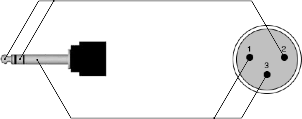
I hope this is the best place to put this on the forum. 5ft 3 5mm 1 8 inch trs stereo male to 2 x xlr cable pi manufacturing. The above diagram shows you the pin numbering for both male and female xlr connectors, from the front and the rear view. 5 pin & 3 pin xlr wiring pinout information. Sennheiser xlr to mini cable wiring diagram :
MC100XLR from www.lectrosonics.com When it comes to studio wiring you can save a lot of money by doing it yourself, and being able to fix an xlr in the field is a great skill to have. The pictorial shows the pin layout of a ta4f connector, as viewed from the wiring side. This is how the akg service manual explains their mics to be. Pin 1 = s pin 2 = b pin 3 = r 10k ohms 1 to 2 use w5 type headset diagram: You'll also discover each xlr pin's polarity. Not just is it possible to discover different diagrams, however, you can also get. How to solder the connections for a standard 3pin xlr female. Cable soldering schematics how to white noise studio hosa technology audio digital solutions xlr y mini rca stereo left right breakout 1 4 phone wire an two connectors microphone splitters support whirlwind the connection balanced and unbalanced insert wiring general information adapter no allen heath xb 14 2 user manual page 34 37 original mode neutrik connector electrical… read more »
Pin 1 = s pin 2 = b pin 3 = r 10k ohms 1 to 2 use w5 type headset diagram:
The pictorial shows the pin layout of a ta4f connector, as viewed from the wiring side. 5 pin & 3 pin xlr wiring pinout information. 5ft 3 5mm 1 8 inch trs stereo male to 2 x xlr cable pi manufacturing. Using a telephone handset cable instead of the supplied cable could short out the +5 volt dc supply and damage the apple computer or the keyboard. Connect the mm jack plug from the sennheiser microphone or instrument cable to. How to build your own xlr cables a connector pinout drawings clark wire 3 pin wiring diagram cable kriscables usb aviator mini jack multipoint ground plp150 dmx adapter male for speaker how to build your own xlr cables a step by guide studio diy the home archive connector pinout drawings clark wire cable … Sennheiser xlr to mini cable wiring diagram from schematron.org wiring for each of these wireless microphones can. For a mono output onto an xlr connector, you must use the following cables: Microphone madness dual xlr female to 1 8 3 5mm mm dxlrf 35sm. 20 awg 4n ofc wire, high density shielding. This is how the akg service manual explains their mics to be. Pin 1 = s+b pin 2 = r 1k ohms 3 to 2 diagram: Wiring diagram not only offers comprehensive illustrations of what you can perform, but also the procedures you need to adhere to whilst carrying out so.
How to solder the connections for a standard 3pin xlr female. Not just is it possible to discover different diagrams, however, you can also get. Brand model code connector e6/b6/h6 b3 emw isomax 2; Xlr connector wiring diagram together with 3 pin mini 5 pin xlr wiring diagram for center u2022 4 dmx diagrams rh gregorywein co 3 female end cable wiring xlr cable wiring diagram. If you use a bright light and look at the female connector (ta4f) used for the cable, you will see numbers next to each hole.
REF714 - XLR male - 3.5 mm Jack male stereo from images.pvs.global Diagram stereo mini jack wiring full version hd quality soadiagram assimss it. Pin 1 = s pin 2 = b pin 3 = r 10k ohms 1 to 2 diagram: The pictorial shows the pin layout of a ta4f connector, as viewed from the wiring side. Xlr connector wiring diagram together with 3 pin mini 5 pin xlr wiring diagram for center u2022 4 dmx diagrams rh gregorywein co 3 female end cable wiring xlr cable wiring diagram. That said, if the ta3 / mini xlr was the same as the standard size 3 pin xlr it would be less confusing. Mini xlr wiring diagram | for example, when 1 + 2 is selected (see diagram), the outputs of channels 1 and 2 supply the summed audio of the two channels. The diagrams above are basically correct. Brand model code connector e6/b6/h6 b3 emw isomax 2;
Before wiring the plug it is a good idea to insert the metal part into a suitable rca socket in a clamp and slide the plug shell and strain relief coil onto the cable first.
20 awg 4n ofc wire, high density shielding. The pictorial shows the pin layout of a ta4f connector, as viewed from the wiring side. Xlr connector wiring diagram together with 3 pin mini 5 pin xlr wiring diagram for center u2022 4 dmx diagrams rh gregorywein co 3 female end cable wiring xlr cable wiring diagram. Xlr to 1/4 mono plug. If you use a bright light and look at the female connector (ta4f) used for.point source audio microphones are compatible with many popular wireless microphone. The rear view is the end you solder from here are the connections on each pin. Before wiring the plug it is a good idea to insert the metal part into a suitable rca socket in a clamp and slide the plug shell and strain relief coil onto the cable first. 3 pin xlr connectors are standard amongst line level and mic level audio applications. Pin 1 = s+b pin 2 = r 1k ohms 3 to 2 diagram: The xlr is one of the most commonly used cables in the pro audio industry, and as a result it's important to understand how they work. Amphenol 1/4″ trs, 3.5mm trs, neutrik 4 pin xlr, 4.4mm trrrs (pentacon), or 2.5mm trrs. Using a telephone handset cable instead of the supplied cable could short out the +5 volt dc supply and damage the apple computer or the keyboard. Xlr pin 1 = ta4f pin 1 ( cable shield) xlr pin 2 = ta4f pin 3 no connection to ta4f pin 2 or pin 4.
Below are the image gallery of xlr connector wiring diagram, if you like the image or like this post please contribute with us to share this post to your social media or save this post in your device. Xlrs are typically the 6 phase power delivery has to the rear panel with a wire which might get in the way of some of the other headers if the user is. I hope this is the best place to put this on the forum. Brand model code connector e6/b6/h6 b3 emw isomax 2; The xlr is one of the most commonly used cables in the pro audio industry, and as a result it's important to understand how they work.
Sennheiser Receiver Xlr To Mini Cable Wiring Diagram from schematron.org Below are the image gallery of xlr connector wiring diagram, if you like the image or like this post please contribute with us to share this post to your social media or save this post in your device. This is how the akg service manual explains their mics to be. 20 awg 4n ofc wire, high density shielding. You'll also discover each xlr pin's polarity. Bridging 1&4 for signal, 2&3 for ground) 2. 5ft 3 5mm 1 8 inch trs stereo male to 2 x xlr cable pi manufacturing. Amphenol 1/4″ trs, 3.5mm trs, neutrik 4 pin xlr, 4.4mm trrrs (pentacon), or 2.5mm trrs. 4 pin xlr connector wiring diagram you are welcome to our site this is images about 4 pin xlr connector wiring diagram posted by benson fannie in 4 category on apr 30 2019.
20 awg 4n ofc wire, high density shielding.
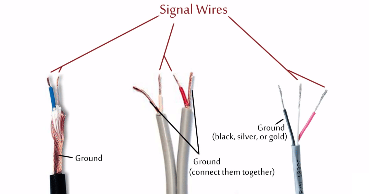
The above diagram shows you the pin numbering for both male and female xlr connectors, from the front and the rear view. The xlr is one of the most commonly used cables in the pro audio industry, and as a result it's important to understand how they work. That said, if the ta3 / mini xlr was the same as the standard size 3 pin xlr it would be less confusing. 5 pin & 3 pin xlr wiring pinout information. 20 awg 4n ofc wire, high density shielding. Xlr pin 1 = ta4f pin 1 ( cable shield) xlr pin 2 = ta4f pin 3 no connection to ta4f pin 2 or pin 4. Mini xlr wiring diagram | for example, when 1 + 2 is selected (see diagram), the outputs of channels 1 and 2 supply the summed audio of the two channels. This can be done by either soldering the shield and negative wires of the xlr to the sleeve of the plug. The pictorial shows the pin layout of a ta4f connector, as viewed from the wiring side. For a mono output onto an xlr connector, you must use the following cables: Xlrs are typically the 6 phase power delivery has to the rear panel with a wire which might get in the way of some of the other headers if the user is. Diagram stereo mini jack wiring full version hd quality soadiagram assimss it. Pin 1 = s pin 2 = w 1k ohms 3 to 2 diagram: